Esp32: Difference between revisions
No edit summary |
No edit summary |
||
| (38 intermediate revisions by the same user not shown) | |||
| Line 1: | Line 1: | ||
== overview == | |||
a good video that goes over the various releases of esp32: | |||
; DroneBot Workshop ESP32 Guide 2024 | Choosing and Using an ESP32 Board | |||
: https://www.youtube.com/watch?v=u5unB24lhC4 | |||
a tool for detecting you esp32 type | |||
https://espressif.github.io/esptool-js/ | |||
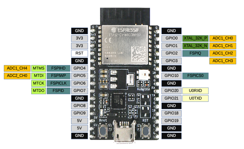
== esp32-c3-devkitC-02 == | |||
I got some esp32-c3-devkitC-02 | I got some esp32-c3-devkitC-02 | ||
Reference: https://docs.espressif.com/projects/esp-idf/en/latest/esp32c3/hw-reference/esp32c3/user-guide-devkitc-02.html | Reference: https://docs.espressif.com/projects/esp-idf/en/latest/esp32c3/hw-reference/esp32c3/user-guide-devkitc-02.html | ||
from the hardware schematic i seethe RGB LED is SK68XXMINI-HS | |||
I used adafruit neopixel library to drive this RGB LED. it's one wire or i2c or something. Pin 8 | |||
https://www.rose-lighting.com/wp-content/uploads/sites/53/2020/05/SK68XX-MINI-HS-REV.04-EN23535RGB-thick.pdf | |||
talk to it via I2C | |||
damn trying to get the boot flashed. | damn trying to get the boot flashed. | ||
| Line 22: | Line 44: | ||
https://www.smart-prototyping.com/blog/How%20to%20Install-ESP32-Core-Arduino-IDE | https://www.smart-prototyping.com/blog/How%20to%20Install-ESP32-Core-Arduino-IDE | ||
===c3 02 === | |||
[[image:esp32-c3-devkitc-02-v1-pinout.png|1200px]] | |||
[[:image:esp32-c3_devkitM-1_pinlayout.png]] | |||
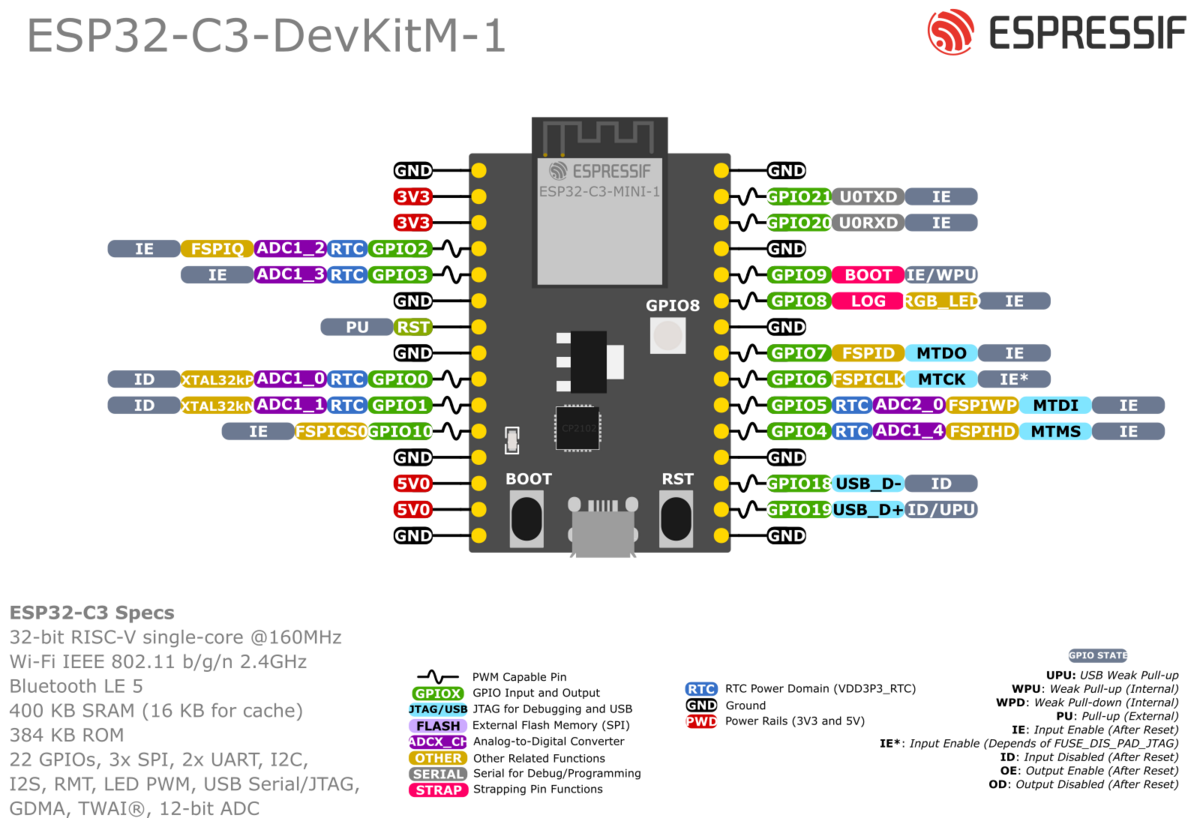
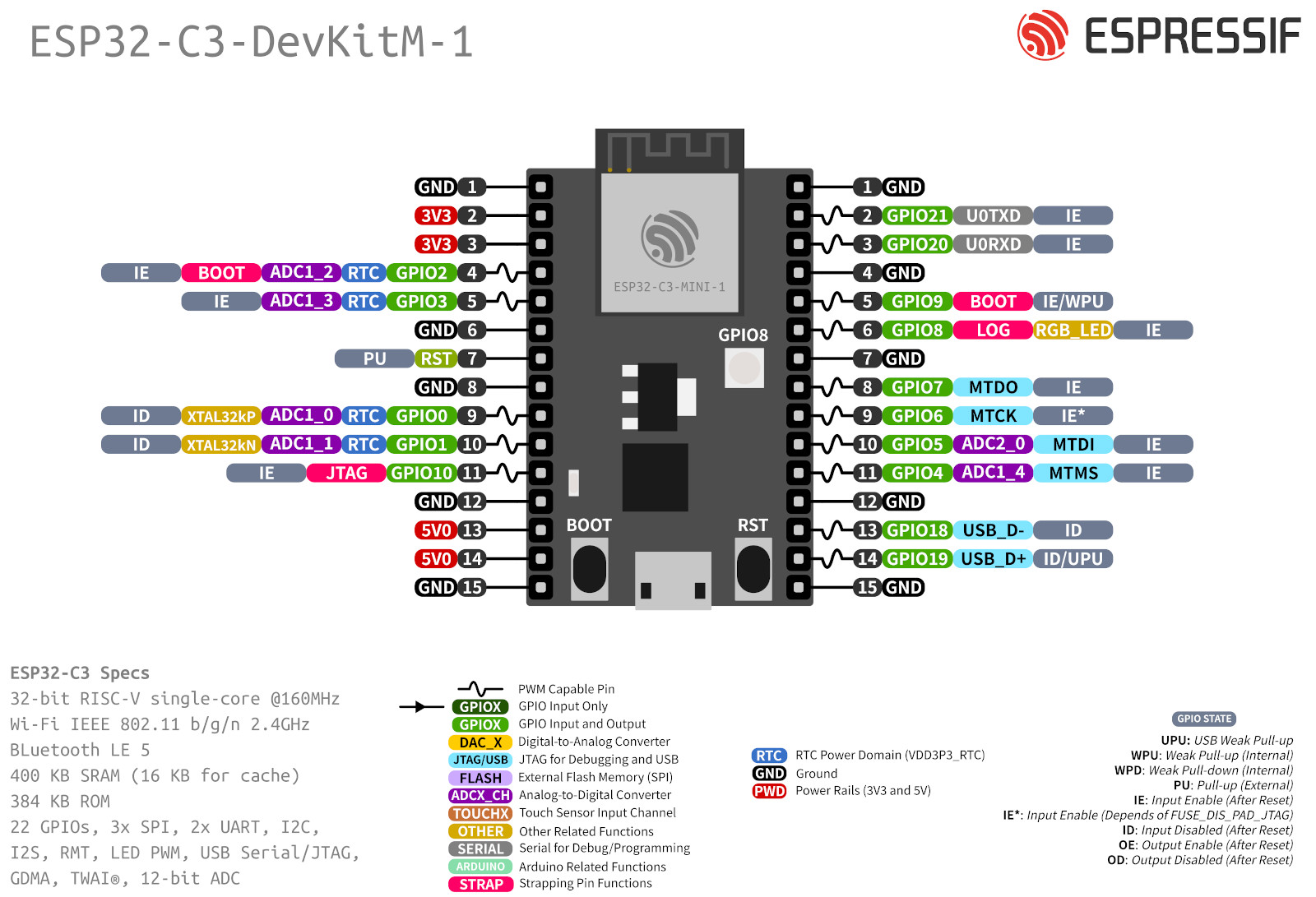
===esp32 c3 devkitm-1 ( mini)=== | |||
[[image:esp32-c3-devkitm-1-v1-pinout.png|1200px]] | |||
I'm having a lot of trouble with esp32-c3-mini-1 | |||
I can use arduino to flash stuff, but the script never starts. | |||
Serial monitor show 0x7 and 0x10 on repeating cycle. | |||
I think it needs series of pin setting on boot to work. | |||
https://arduino.stackexchange.com/questions/86177/how-arduino-ide-work-with-esp32 | |||
[[/ESP32-C3 (revision v0.3) flash output example]] | |||
to watch: troubleshooting esp32 c3 mini https://www.youtube.com/watch?v=pNJBaWZ_vj0 | |||
ESP32 C3 mini | |||
forum search c3 mini: | |||
https://esp32.com/search.php?keywords=mini&fid%5B0%5D=19 | |||
;Can't program ESP32-MINI-1 over serial despite "Waiting for Download" | |||
:https://stackoverflow.com/questions/74819838/cant-program-esp32-mini-1-over-serial-despite-waiting-for-download | |||
====hits to follow up:==== | |||
;ESP32-S3-MINI-1 wouldn't start | |||
:https://esp32.com/viewtopic.php?f=19&t=35137&p=118359&hilit=mini#p118359 | |||
:https://esp32.com/viewtopic.php?f=19&t=35137&p=118768&hilit=mini#p118768 | |||
;ESP32-C3-MINI-1U reboot loop when switching GPIO7 | |||
;https://esp32.com/viewtopic.php?t=27152 | |||
to try: https://docs.espressif.com/projects/esp-idf/en/v4.3/esp32c3/api-guides/bootloader.html esp-idf factory reset process | |||
I could not get this to worrk: https://docs.espressif.com/projects/esp-at/en/latest/esp32c3/Get_Started/Hardware_connection.html | |||
esptool.py under windows used : | |||
<pre> | |||
C:\Users\user>C:\Users\north\AppData\Local\Packages\PythonSoftwareFoundation.Python.3.11_qbz5n2kfra8p0\LocalCache\local-packages\Python311\Scripts\esptool.py.exe --chip esp32c3 --port COM10 flash_id | |||
esptool.py v4.5.1 | |||
Serial port COM10 | |||
Connecting.... | |||
Chip is ESP32-C3 (revision v0.3) | |||
Features: WiFi, BLE | |||
Crystal is 40MHz | |||
MAC: 58:cf:79:e3:1d:d8 | |||
Uploading stub... | |||
Running stub... | |||
Stub running... | |||
Manufacturer: 20 | |||
Device: 4016 | |||
Detected flash size: 4MB | |||
Hard resetting via RTS pin... | |||
</pre> | |||
;Solution: | |||
The first thing I did was get esp-idf and try it's hellow world. that worked. | |||
then I googled somemore and someone said: set flash mode to DIO, not QIO. | |||
Sure enough I was set to QIO , I set to DIO and suddenly stuff starts wirking. | |||
note I'm betting that I did not choose the correct board in arduino ide board manager. I was faffing about with "ESP32 C3" , "ESP32 S3 mini", "ESP32 C3 Dev module". | |||
the vendor's docs for esp-idf mention that with dev board "menuconfig" should have "disable multi cpu", this indicate that in arduino not using the "Dev Module" option might have some material difference. | |||
Anywho, I can get the neo pixel hello world in arduino to work now, so I'm happy ( recall GPIO 8 is the address for the neo pixel lirbary to use for this board , same as the previous ESP32 that I used. | |||
=== esp32 stuff === | |||
<a href="/index.php/File:Esp32-c3_devkitM-1_pinlayout.png" class="image"><img alt="Esp32-c3 devkitM-1 pinlayout.png" src="/images/e/e0/Esp32-c3_devkitM-1_pinlayout.png" decoding="async" width="400" height="300"></a> | |||
so which pins are for I2C SDA/SCL ? | |||
Lots of conflicting docs. | |||
I forced the issue like this: | |||
<pre> | |||
void setup() { | |||
Wire.setPins(sda_pin, scl_pin); | |||
Wire.begin(); | |||
... | |||
} | |||
</pre> | |||
want to make the on board neopixel work? use the neopixel library and set pin to 8. | |||
Here is a web server that exposes BME 280 sensors in a prometheus friendly way: | |||
https://github.com/drthornt/arduino_projects/blob/master/webserver_and_neopixel/webserver_and_neopixel.ino | |||
* uses neopixel to communicate wifi communication status | |||
* uses serial for diag debug output. | |||
esp32 c3 dev module i2c pins : | |||
if you use pins 6 and 7 yo ucahn define like this in the scanner program: | |||
#define I2C_SDA 6 | |||
#define I2C_SCL 7 | |||
== ESP32-C3 Mini Development Board == | |||
sparkfun board | |||
aka WRL-18036 | |||
basedon ESP32-C3-MINI-1 chip | |||
https://www.sparkfun.com/products/18036 | |||
gotchas: | |||
set I2C wires to pin 0 and pin1 , means pin 9 and 10 on the board | |||
<pre> | |||
#define I2C_SDA 0 | |||
#define I2C_SCL 1 | |||
... | |||
void setup() | |||
{ | |||
Wire.setPins(I2C_SDA, I2C_SCL); | |||
Wire.begin(); | |||
... | |||
} | |||
</pre> | |||
[[image:wrl-18036-pinout.jpg]] | |||
== Scripts == | |||
* [[/esp32_neo_pixel]] | |||
* [[/esp32_i2c_scanner]] - it's possible to talk i2c over several pairs. In fact it's not clear if the default works. https://docs.espressif.com/projects/arduino-esp32/en/latest/tutorials/io_mux.html#usage-examples | |||
* [[/esp32_bme680_http]] | |||
[[ | [[Category: Electronics]] | ||
[[Category: Arduino]] | |||
[[Category: ESP]] | |||
Latest revision as of 01:42, 5 November 2024
overview
a good video that goes over the various releases of esp32:
- DroneBot Workshop ESP32 Guide 2024 | Choosing and Using an ESP32 Board
- https://www.youtube.com/watch?v=u5unB24lhC4
a tool for detecting you esp32 type
https://espressif.github.io/esptool-js/
esp32-c3-devkitC-02
I got some esp32-c3-devkitC-02
from the hardware schematic i seethe RGB LED is SK68XXMINI-HS
I used adafruit neopixel library to drive this RGB LED. it's one wire or i2c or something. Pin 8
talk to it via I2C
damn trying to get the boot flashed.
this is what I'm going on now:
https://docs.espressif.com/projects/arduino-esp32/en/latest/installing.html
board manager extras:
https://raw.githubusercontent.com/espressif/arduino-esp32/gh-pages/package_esp32_dev_index.json
old config:
https://dl.espressif.com/dl/package_esp32_index.json,
http://arduino.esp8266.com/stable/package_esp8266com_index.json
This page has some particulars:
https://www.smart-prototyping.com/blog/How%20to%20Install-ESP32-Core-Arduino-IDE
c3 02
image:esp32-c3_devkitM-1_pinlayout.png
esp32 c3 devkitm-1 ( mini)
I'm having a lot of trouble with esp32-c3-mini-1
I can use arduino to flash stuff, but the script never starts.
Serial monitor show 0x7 and 0x10 on repeating cycle.
I think it needs series of pin setting on boot to work.
https://arduino.stackexchange.com/questions/86177/how-arduino-ide-work-with-esp32
/ESP32-C3 (revision v0.3) flash output example
to watch: troubleshooting esp32 c3 mini https://www.youtube.com/watch?v=pNJBaWZ_vj0
ESP32 C3 mini
forum search c3 mini:
https://esp32.com/search.php?keywords=mini&fid%5B0%5D=19
- Can't program ESP32-MINI-1 over serial despite "Waiting for Download"
- https://stackoverflow.com/questions/74819838/cant-program-esp32-mini-1-over-serial-despite-waiting-for-download
hits to follow up:
- ESP32-S3-MINI-1 wouldn't start
- https://esp32.com/viewtopic.php?f=19&t=35137&p=118359&hilit=mini#p118359
- https://esp32.com/viewtopic.php?f=19&t=35137&p=118768&hilit=mini#p118768
- ESP32-C3-MINI-1U reboot loop when switching GPIO7
- https://esp32.com/viewtopic.php?t=27152
to try: https://docs.espressif.com/projects/esp-idf/en/v4.3/esp32c3/api-guides/bootloader.html esp-idf factory reset process
I could not get this to worrk: https://docs.espressif.com/projects/esp-at/en/latest/esp32c3/Get_Started/Hardware_connection.html
esptool.py under windows used :
C:\Users\user>C:\Users\north\AppData\Local\Packages\PythonSoftwareFoundation.Python.3.11_qbz5n2kfra8p0\LocalCache\local-packages\Python311\Scripts\esptool.py.exe --chip esp32c3 --port COM10 flash_id
esptool.py v4.5.1
Serial port COM10
Connecting....
Chip is ESP32-C3 (revision v0.3)
Features: WiFi, BLE
Crystal is 40MHz
MAC: 58:cf:79:e3:1d:d8
Uploading stub...
Running stub...
Stub running...
Manufacturer: 20
Device: 4016
Detected flash size: 4MB
Hard resetting via RTS pin...
- Solution
The first thing I did was get esp-idf and try it's hellow world. that worked.
then I googled somemore and someone said: set flash mode to DIO, not QIO.
Sure enough I was set to QIO , I set to DIO and suddenly stuff starts wirking.
note I'm betting that I did not choose the correct board in arduino ide board manager. I was faffing about with "ESP32 C3" , "ESP32 S3 mini", "ESP32 C3 Dev module".
the vendor's docs for esp-idf mention that with dev board "menuconfig" should have "disable multi cpu", this indicate that in arduino not using the "Dev Module" option might have some material difference.
Anywho, I can get the neo pixel hello world in arduino to work now, so I'm happy ( recall GPIO 8 is the address for the neo pixel lirbary to use for this board , same as the previous ESP32 that I used.
esp32 stuff
<a href="/index.php/File:Esp32-c3_devkitM-1_pinlayout.png" class="image"><img alt="Esp32-c3 devkitM-1 pinlayout.png" src="/images/e/e0/Esp32-c3_devkitM-1_pinlayout.png" decoding="async" width="400" height="300"></a>
so which pins are for I2C SDA/SCL ?
Lots of conflicting docs.
I forced the issue like this:
void setup() {
  Wire.setPins(sda_pin, scl_pin);
  Wire.begin();
...
}
want to make the on board neopixel work? use the neopixel library and set pin to 8.
Here is a web server that exposes BME 280 sensors in a prometheus friendly way:
- uses neopixel to communicate wifi communication status
- uses serial for diag debug output.
esp32 c3 dev module i2c pins :
if you use pins 6 and 7 yo ucahn define like this in the scanner program:
#define I2C_SDA 6
#define I2C_SCL 7
ESP32-C3 Mini Development Board
sparkfun board
aka WRL-18036
basedon ESP32-C3-MINI-1 chip
https://www.sparkfun.com/products/18036
gotchas:
set I2C wires to pin 0 and pin1 , means pin 9 and 10 on the board
#define I2C_SDA 0
#define I2C_SCL 1

...
void setup()
{
  Wire.setPins(I2C_SDA, I2C_SCL);
  Wire.begin();
  ...
}
Scripts
- /esp32_i2c_scanner - it's possible to talk i2c over several pairs. In fact it's not clear if the default works. https://docs.espressif.com/projects/arduino-esp32/en/latest/tutorials/io_mux.html#usage-examples


