ESP8266 serial WIFI wireless module: Difference between revisions
(→Links) |
(→Links) |
||
| Line 222: | Line 222: | ||
* wiki https://github.com/esp8266/esp8266-wiki/ | * wiki https://github.com/esp8266/esp8266-wiki/ | ||
* http://benlo.com/esp8266/esp8266QuickStart.html | |||
Revision as of 05:13, 24 April 2016
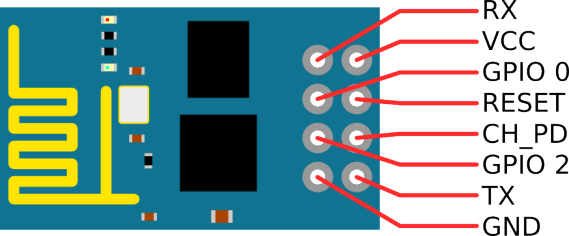
image cheat
overview
default baud ( pre OS ) is : 76880
picked up 3 3.3 v versions of these. It's been fun trying to get them to work.
1. the 3.3v fdti seems to be 5v
2. the firmware seems bust:
<Crazy garbage characters>
Ai-Thinker Technology Co. Ltd.

invalid
then I enter:
AT+RST
and get
ERROR
going to try and find an updated firmware and flash it.
---
time passes, I enter , stage left.
I found the firware on a dodgey looking site. http://arduino-er.blogspot.ca/2015/05/flash-esp8266-firmware-using-esptoolpy.html
python esptool.py -p /dev/ttyUSB0 write_flash 0x000000 "AI-v0.9.5.0 AT Firmware.bin"
Had to make sure that ch_pd was to ground and gpio_0 was high ( vcc)
setserial -g /dev/ttyUSB0
/dev/ttyUSB0, UART: unknown, Port: 0x0000, IRQ: 0, Flags: low_latency
screen /dev/ttyUSB0
and now I get much better results:
AT

OK
AT+RST

OK
Ok, so now I've done my flasshing , how to I get it to operate?
28800 baud , connect ch_pd to vcc ( 3.3v )
then:
<���þ���ú���ð������8:þj¤ÔHÈUÖKºÝݹ
¥µ¢¡¥¹É¹�½µ5Rj¤4Ej
U®®ZËKrÊrªB�ÅJj¤4ê«�W«��$('QY,H¦MH14, 21:50:58
ready
ATAT+RSTATAT
ERROR
AT+RST
OK
c_ÇÏR[¶fJ[:fJSjîóÂOÂGÇWËj¤ÔHÈUÖKºÝݹ
¥µ¢¡¥¹É¹�½µ5Rj¤4Ej
U®®ZËKrÊrªB�ÅJj¤4ê«�W«��$('QY,H¦MH14, 21:50:58
ready
AT
OK
AT
OK
AT+CWLAP
ERROR
AT+CWMODE
ERROR
AT+CWMODE=?
+CWMODE:(1-3)
OK
AT+CWMODE=1
OK
AT+CWLAP
+CWLAP:(3,"sashed_pirate",-75,"dc:fb:02:08:41:10",1)
+CWLAP:(4,"tuxedo",-47,"00:0e:8e:3f:ff:7a",1)
+CWLAP:(4,"ShyWhale",-87,"0c:47:3d:c6:ff:08",1)
+CWLAP:(0,"ShyWhale-guest",-89,"0c:47:3d:c6:ff:0c",1)
+CWLAP:(4,"Rogers06555",-87,"0c:47:3d:2c:32:68",1)
+CWLAP:(3,"dobber_w",-71,"00:23:69:98:06:8d",6)
+CWLAP:(3,"BELL500",-71,"44:e9:dd:46:e9:2a",6)
+CWLAP:(3,"TheGinge",-82,"6c:70:9f:ed:df:5c",6)
+CWLAP:(3,"TheBeaver",-82,"7e:70:9f:ed:df:5c",6)
+CWLAP:(3,"TheGinge",-82,"28:cf:e9:85:e5:54",6)
+CWLAP:(3,"TheBeaver",-83,"2a:cf:e9:85:e5:54",6)
+CWLAP:(3,"gopher",-48,"00:16:b6:cc:4a:51",11)
+CWLAP:(3,"1WI2U9WC",-82,"10:0d:7f:4a:10:db",11)
OK
AT+CWJAP="gopher","XXX"
OK
AT+CWJAP?
+CWJAP:"gopher"
OK
AT+CIPSTATUS
STATUS:2
OK
AT+CWJAP?
+CWJAP:"gopher"
OK
AT+CIFSR=?
OK
AT+CIFSR
+CIFSR:STAIP,"192.168.1.119"
+CIFSR:STAMAC,"18:fe:34:f3:02:92"
OK
esp-12-f
references:
- http://www.instructables.com/id/Getting-Started-with-the-ESP8266-ESP-12/?ALLSTEPS
- http://www.instructables.com/id/Programming-the-ESP8266-12E-using-Arduino-software/
- https://github.com/esp8266/Arduino
- http://www.electrodragon.com/w/ESP-12F_ESP8266_Wifi_Board
- https://drive.google.com/folderview?id=0B3dUKfqzZnlwRjFaNTUzZFptbzg&usp=drive_web
- firmware:
- at_v0.20_14_11_28.zip
wires
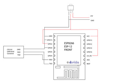
You need to connect a few GPIO pins on the ESP-12 to 3.3V or Ground, to set it in the right mode for communicating with it. Here are the connections you need to make :
VCC ----> 3.3V Power supply (Vout of LM1117)
GND ----> Ground of power supply
CH_PD ----> HIGH (3.3V)
GPIO2 ----> HIGH (3.3V)
GPIO15 ----> LOW (GND)
GPIO0 ----> HIGH or Floating for AT Mode (3.3V) [ * if you want to flash completely different firmware then you must connect it to ground ]
IMPORTANT: In order to update your ESP8266 to the latest firmware version available, you need to change your circuit! GPIO 0 must be connected to GND pin.
Serial
First, to check if the module has been recognised and is accepting commands, just briefly connect the "REST" pin of the ESP-12 to ground, using a jumper. This resets the ESP-12 and you should see something like the screenshot if this works well.
Next, we run the following set of commands in the Serial Terminal:
1. AT
This is just a hello message, and if the ESP-12 is in the correct mode, it will return an "OK" message.
2. AT+GMR
This command returns the firmware version currently on the chip.
3. AT+CWMODE?
This command returns the mode of operation. If the mode is not 3, we will change it to 3 using the following command :
AT+CWMODE=3
This mode makes the ESP8266 behave both as a WiFi client as well as a WiFi Access point.
4. AT+CWLAP
The LAP (List Access Points) lists the WiFi networks around. Next, we choose our WiFi network
5. AT+CWJAP="your_network_name","your_wifi_network_password"
This command JAP (Join Access Point) makes the ESP-12 join your WiFi Network.
6. AT+CIFSR
This command returns the IP address of the ESP-12 as the second line and the gateway IP address as the first line if it managed to connect successfully.
Arduino blink wiring
File:Esp-12-arduino-blink-schematic schem-960px.png
Links
- russian site about the 0.9.5.0 firmware http://esp8266.ru/esp8266-sdk-0-9-5-v0-21/
- thread on recommended firmware: http://www.esp8266.com/viewtopic.php?f=6&t=2219 ( circa Tue Mar 31, 2015 )
- video on how to write new firmware https://www.youtube.com/watch?v=PycRnjcXMRI
- esptool for writing firmware https://github.com/themadinventor/esptool
google searches of note:
+site:hackaday.com esp firmware
- step by step firmware: http://blog.randypatterson.com/esp8266-firmware-updates-and-options/


