ESP8266 serial WIFI wireless module: Difference between revisions
(→wires) |
|||
| Line 156: | Line 156: | ||
=== wires === | === wires === | ||
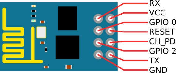
Looking at the (8 pin) board from the top (chips and antenna side), with the antenna to the right, the pins from the top down in the edge row are: | |||
TXD (goes to the 3.3V RxI of the UART USB adapter to the PC) | |||
CH_PD (enable/power down, must be pulled to 3.3v directly or via resistor) | |||
REST (reset, must be pulled to 3.3v) | |||
VCC (3.3v power supply) | |||
The inner row (top and bottom have square pads) | |||
GND (connect to power ground) | |||
GPIO 2 | |||
GPIO 0 (leave open or pull up for normal, pull down to upload new firmware) | |||
RXD (goes to the 3.3V TxO of the UART USB adapter to the PC) | |||
===Serial === | ===Serial === | ||
Revision as of 22:27, 12 September 2016
image cheat
overview
default baud ( pre OS ) is : 76880
picked up 3 3.3 v versions of these. It's been fun trying to get them to work.
1. the 3.3v fdti seems to be 5v
2. the firmware seems bust:
<Crazy garbage characters>
Ai-Thinker Technology Co. Ltd.

invalid
then I enter:
AT+RST
and get
ERROR
going to try and find an updated firmware and flash it.
---
time passes, I enter , stage left.
I found the firware on a dodgey looking site. http://arduino-er.blogspot.ca/2015/05/flash-esp8266-firmware-using-esptoolpy.html
python esptool.py -p /dev/ttyUSB0 write_flash 0x000000 "AI-v0.9.5.0 AT Firmware.bin"
Had to make sure that ch_pd was to ground and gpio_0 was high ( vcc)
setserial -g /dev/ttyUSB0
/dev/ttyUSB0, UART: unknown, Port: 0x0000, IRQ: 0, Flags: low_latency
screen /dev/ttyUSB0
and now I get much better results:
AT

OK
AT+RST

OK
Ok, so now I've done my flasshing , how to I get it to operate?
28800 baud , connect ch_pd to vcc ( 3.3v )
then:
<���þ���ú���ð������8:þj¤ÔHÈUÖKºÝݹ
¥µ¢¡¥¹É¹�½µ5Rj¤4Ej
U®®ZËKrÊrªB�ÅJj¤4ê«�W«��$('QY,H¦MH14, 21:50:58
ready
ATAT+RSTATAT
ERROR
AT+RST
OK
c_ÇÏR[¶fJ[:fJSjîóÂOÂGÇWËj¤ÔHÈUÖKºÝݹ
¥µ¢¡¥¹É¹�½µ5Rj¤4Ej
U®®ZËKrÊrªB�ÅJj¤4ê«�W«��$('QY,H¦MH14, 21:50:58
ready
AT
OK
AT
OK
AT+CWLAP
ERROR
AT+CWMODE
ERROR
AT+CWMODE=?
+CWMODE:(1-3)
OK
AT+CWMODE=1
OK
AT+CWLAP
+CWLAP:(3,"sashed_pirate",-75,"dc:fb:02:08:41:10",1)
+CWLAP:(4,"tuxedo",-47,"00:0e:8e:3f:ff:7a",1)
+CWLAP:(4,"ShyWhale",-87,"0c:47:3d:c6:ff:08",1)
+CWLAP:(0,"ShyWhale-guest",-89,"0c:47:3d:c6:ff:0c",1)
+CWLAP:(4,"Rogers06555",-87,"0c:47:3d:2c:32:68",1)
+CWLAP:(3,"dobber_w",-71,"00:23:69:98:06:8d",6)
+CWLAP:(3,"BELL500",-71,"44:e9:dd:46:e9:2a",6)
+CWLAP:(3,"TheGinge",-82,"6c:70:9f:ed:df:5c",6)
+CWLAP:(3,"TheBeaver",-82,"7e:70:9f:ed:df:5c",6)
+CWLAP:(3,"TheGinge",-82,"28:cf:e9:85:e5:54",6)
+CWLAP:(3,"TheBeaver",-83,"2a:cf:e9:85:e5:54",6)
+CWLAP:(3,"gopher",-48,"00:16:b6:cc:4a:51",11)
+CWLAP:(3,"1WI2U9WC",-82,"10:0d:7f:4a:10:db",11)
OK
AT+CWJAP="gopher","XXX"
OK
AT+CWJAP?
+CWJAP:"gopher"
OK
AT+CIPSTATUS
STATUS:2
OK
AT+CWJAP?
+CWJAP:"gopher"
OK
AT+CIFSR=?
OK
AT+CIFSR
+CIFSR:STAIP,"192.168.1.119"
+CIFSR:STAMAC,"18:fe:34:f3:02:92"
OK
esp-12-f
references:
- http://www.instructables.com/id/Getting-Started-with-the-ESP8266-ESP-12/?ALLSTEPS
- http://www.esp8266.com/wiki/doku.php?id=getting-started-with-the-esp8266
- http://www.instructables.com/id/Programming-the-ESP8266-12E-using-Arduino-software/
- https://github.com/esp8266/Arduino
- http://www.electrodragon.com/w/ESP-12F_ESP8266_Wifi_Board
- https://drive.google.com/folderview?id=0B3dUKfqzZnlwRjFaNTUzZFptbzg&usp=drive_web
- firmware:
- at_v0.20_14_11_28.zip
wires
Looking at the (8 pin) board from the top (chips and antenna side), with the antenna to the right, the pins from the top down in the edge row are:
TXD (goes to the 3.3V RxI of the UART USB adapter to the PC)
CH_PD (enable/power down, must be pulled to 3.3v directly or via resistor)
REST (reset, must be pulled to 3.3v)
VCC (3.3v power supply)
The inner row (top and bottom have square pads)
GND (connect to power ground)
GPIO 2
GPIO 0 (leave open or pull up for normal, pull down to upload new firmware)
RXD (goes to the 3.3V TxO of the UART USB adapter to the PC)
Serial
First, to check if the module has been recognised and is accepting commands, just briefly connect the "REST" pin of the ESP-12 to ground, using a jumper. This resets the ESP-12 and you should see something like the screenshot if this works well.
Next, we run the following set of commands in the Serial Terminal:
1. AT
This is just a hello message, and if the ESP-12 is in the correct mode, it will return an "OK" message.
2. AT+GMR
This command returns the firmware version currently on the chip.
3. AT+CWMODE?
This command returns the mode of operation. If the mode is not 3, we will change it to 3 using the following command :
AT+CWMODE=3
This mode makes the ESP8266 behave both as a WiFi client as well as a WiFi Access point.
4. AT+CWLAP
The LAP (List Access Points) lists the WiFi networks around. Next, we choose our WiFi network
5. AT+CWJAP="your_network_name","your_wifi_network_password"
This command JAP (Join Access Point) makes the ESP-12 join your WiFi Network.
6. AT+CIFSR
This command returns the IP address of the ESP-12 as the second line and the gateway IP address as the first line if it managed to connect successfully.
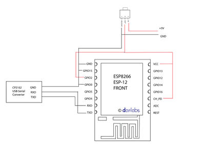
Arduino blink wiring
File:Esp-12-arduino-blink-schematic schem-960px.png
Links
- russian site about the 0.9.5.0 firmware http://esp8266.ru/esp8266-sdk-0-9-5-v0-21/
- thread on recommended firmware: http://www.esp8266.com/viewtopic.php?f=6&t=2219 ( circa Tue Mar 31, 2015 )
- video on how to write new firmware https://www.youtube.com/watch?v=PycRnjcXMRI
- esptool for writing firmware https://github.com/themadinventor/esptool
google searches of note:
+site:hackaday.com esp firmware
- step by step firmware: http://blog.randypatterson.com/esp8266-firmware-updates-and-options/


